


Hydraulic Pump Troubleshooting: Diagnosing Low Pressure, Cavitation & Overheating
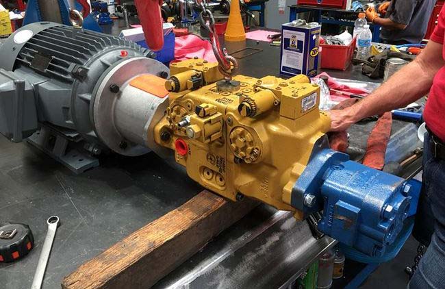
When an industrial hydraulic system begins losing cycle speed, whining abnormally, or tripping out on oil temperature, maintenance crews frequently jump to replacing the hydraulic pump immediately. However, industry diagnostic records show that over 60% of pumps removed from service were operating normally—the underlying issue stemmed from an unseated relief valve, aerated reservoir fluid, or a clogged suction line.
This technical guide provides a systematic, step-by-step diagnostic workflow developed by NN Hydraulic India's fluid power rebuild specialists to isolate the genuine root cause before removing heavy machinery offline.
1. Diagnosing Low System Pressure: Pump Slippage vs. Relief Valve Failure
Hydraulic pumps do not create pressure; they create fluid flow. Pressure is only generated when fluid flow encounters mechanical resistance. When system pressure fails to build up to the operating setpoint under load, you must determine whether the pump cannot deliver rated flow (internal slippage) or if the fluid is bypassing prematurely through a relief valve or directional valve spool.
The Hydraulic Pump "Block Test" Procedure
Step 1: Safely depressurize and lock out the hydraulic circuit. Disconnect the main pressure line immediately downstream of the pump.
Step 2: Install a calibrated high-pressure inline flow meter accompanied by an adjustable needle relief valve and a 0–400 bar calibrated pressure gauge.
Step 3: Direct the meter return hose directly back into the reservoir below fluid level.
Step 4: Start the prime mover and record pump flow at minimum pressure. Gradually throttle the needle valve to increase pressure toward the pump's rated operating point (e.g. 210 bar or 280 bar).
Conclusion: If flow drops by more than 10%–15% as pressure increases to rated setting, the pump has excessive internal clearance wear (cylinder block face, valve plate, or piston rings) and requires overhaul. If flow remains steady under full load, the pump is healthy, and the fault lies downstream in system valves or actuators.
2. Cavitation vs. Aeration: How to Accurately Distinguish Them
Both cavitation and aeration produce a distinct, loud rattling or gravel-grinding sound inside the pump housing, accompanied by erratic actuator motion. Distinguishing between them is vital because their remedies are completely opposite:
- Aeration (Air Ingress): Air is drawn into the hydraulic oil from outside the system. Symptoms include a spongy or foaming oil reservoir, milky fluid discoloration, and erratic actuator chatter. Common causes include loose suction flange fittings, cracked suction hoses, or a deteriorated pump drive-shaft lip seal.
- Cavitation (Fluid Vaporization): Occurs when the absolute pressure at the pump inlet drops below the vapor pressure of the hydraulic oil, causing microscopic vapor cavities to form and violently collapse against the cylinder barrel and valve plate. The reservoir oil remains clear, but the pump runs burning hot and sounds like marble balls rattling inside.
Expert Tip: Inlet Vacuum Verification
Install a compound vacuum gauge directly at the pump suction port. At normal operating oil temperature (50°C), inlet vacuum should never exceed 5 in. Hg (0.17 bar vacuum) for mineral oils. Readings exceeding 7–10 in. Hg indicate restricted inlet strainers, undersized suction plumbing, cold oil viscosity issues, or an inlet shut-off valve inadvertently throttled.
3. Diagnosing Excessive Fluid Temperature & Pump Overheating
Operating hydraulic oil temperatures should ideally stabilize between 45°C and 60°C. Sustained operation above 70°C drastically reduces fluid viscosity, degrades elastomers and seals, and accelerates metal-to-metal boundary friction.
In variable displacement axial piston pumps (such as Rexroth A10VSO, Sauer Danfoss Series 90, or Kawasaki K3V), the most reliable diagnostic indicator of internal health is the case drain line:
- Case drain flow represents the internal lubricating leakage across the barrel face, pistons, and swashplate bearings.
- Under deadhead / maximum pressure compensation, healthy case drain flow should not exceed 3% to 5% of the pump's maximum rated displacement.
- If the case drain line is scalding hot to the touch compared to the tank return line, or if drain volume spikes significantly, internal rotating groups are worn and bypassing high-pressure energy directly into heat.
4. Quick Hydraulic Pump Fault Diagnostic Matrix
Refer to this quick troubleshooting reference table during field inspections:
| Observed Symptom | Probable Root Cause | Verification Check | Corrective Action |
|---|---|---|---|
| Pump whines loudly; fluid foaming in sight glass | Suction aeration / air entry | Spray oil around shaft seal & suction fittings; listen for pitch change | Tighten suction clamps; replace shaft oil seal; bleed air from lines |
| Pump noisy; reservoir oil clear and clean | Inlet cavitation / fluid starvation | Check inlet vacuum gauge; inspect suction strainer for clogging | Clean or replace suction filter; inspect inlet shut-off valve; warm up oil |
| Actuators move slowly; pressure drops under load | Internal pump slippage or stuck relief valve | Perform flow meter block test; measure case drain leakage | Lap or replace valve plate & barrel; clean or replace relief cartridge |
| Rapid overheating; hot case drain pipe | High-pressure internal leakage or clogged heat exchanger | Measure delta temperature across cooler; measure case drain GPM | Clean heat exchanger fins; replace worn rotating group; refill ISO VG 46/68 |
| Shaft seal blows out repeatedly | Excessive case pressure | Inspect case drain line for kinks, check valves, or undersized tubing | Ensure case drain line returns unpressurized directly to tank below oil level |
5. Need Professional Bench Testing or Emergency Rebuild?
If on-site diagnostics indicate internal pump damage, continued operation can contaminate your entire hydraulic reservoir with microscopic bronze and hardened steel particles, damaging proportional valves and cylinders throughout your plant.
At NN Hydraulic India, our dedicated fluid power facility in New Delhi is equipped with digital hydrostatic test benches capable of simulating full pressure loads up to 400 bar and 500 LPM flow. We stock genuine replacement parts and complete rotating groups for Rexroth, Parker, Kawasaki, Danfoss, Caterpillar, Eaton, and Liebherr hydraulic equipment.